HOME INSTALLATION INSTRUCTIONS
T-5 Adapter for 49-64 Ford 3 and 4 speed bellhousings
PILOT PORTION OF INPUT SHAFT MUST BE SHORTENED ON ALL APPLICATIONS
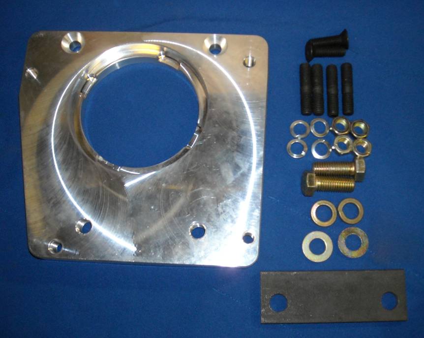
Adapter plate to mount 1985-1993 Ford Mustang T-5 transmission on 1949-1964 Ford Passenger car bellhousings. Includes mounting hardware.
· Do not attempt to use 94 or newer T-5 in a car application as the input shaft is longer.
· The adapter can be used with 215-223 6 cylinder, Y-Block V-8, some Flathead V-8, FE series and 1962-1964 260-289 small block bellhousings.
· This kit is not designed for use with Y-Block powered trucks with ‘85-’93 transmissions.
Clutch disc. A new clutch disc with 1-1/16” 10 spline hub must replace the original.
Diameter must match your pressure plate, typically 10” or 11”.
Pressure plate. The original pressure plate can be re-used if in good condition.
Clutch fork. The original clutch fork can be re-used if in good condition.
Release bearing. The original release bearing can be re-used if in good condition.
Flywheel. Surface the flywheel and replace ring gear if needed.
Pilot bearing. The pilot portion of V-8 and V-6 T-5’s is the same as the original @ .668”.
On 4 cylinder T-5’s the pilot is .590”. For the 4-cylinder transmission it is recommended that the press-in needle bearing
of a 4 cylinder pilot bearing be installed in an original bushing. The original bushing must be bored to accept the needle bearing pilot.
Shifter. On Thunderbirds and 1957-later sedans the shifter will clear a bench seat.
On 1954-56 sedans the lever may need to be bent. Shifter location 2” toward the center of stock on T-Birds.
Drive shaft yoke The yoke will need to be replaced as the spline is different. 26 spline required, commonly referred to as a C-4 yoke.
A 1966 Mustang yoke will work for many applications.
Rear mount Use 1979-’93 Mustang rear mount. Adapter locates the mount in the level position.
Installation:
· Disconnect the battery. Elevate vehicle and block wheels. Use appropriate jack stands and safety measures.
Support the back of the engine as the transmission supports the rear of the engine. Remove original transmission from vehicle.
The bellhousing can be left on the engine but installation will be easier with it removed.
The clutch disc will need to be replaced as the spline is different. Carefully inspect the pilot bearing and throw-out bearing.
· Replace worn parts as required. Use alignment tool to center clutch disc between flywheel and pressure plate.
Springs in center of the disc face away from flywheel. Tighten pressure plate bolts using diagonal pattern.
Flywheel and pressure plate bolts are special, do not substitute standard grade bolts.
· Mount the adapter to the bellhousing. Place the adapter on the back of the bellhousing with the countersunk holes showing.
Mount adapter to bellhousing with countersunk screws. Use transfer punch to locate new holes in bellhousing. REMOVE ADAPTER.
Drill 2 holes for 9/16” bolts. Replace adapter. The 9/16” bolts are installed inside the bellhousing through the stiffening plate
and thread into the adapter. Loctite and tighten the countersunk screws and 9/16” bolts to 45 ft lbs
. Loctite the studs and hand tighten into the 7/16” holes in the adapter.
The pilot bearing portion of the input shaft must be shortened approximately 3/16” with a disc grinder or other suitable means
rotating shaft while grinding. If the input shaft butts in the rear of crankshaft engine damage will occur.
Check for crankshaft end-play with transmission installed. This dimension must be .004”-.010”.
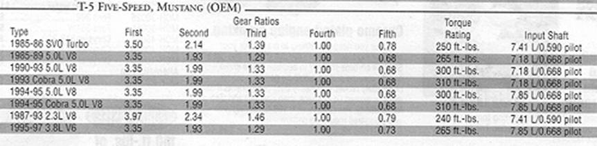
Due to the various input shaft lengths as shown in the chart and varying depths of the recess in the crankshaft no set dimension can be given.
To measure, insert transmission into bellhousing with adapter in place and gently snug the fasteners.
Do not tighten. Measure the distance between the transmission face and mating surface of the bellhousing. Remove this amount + 1/16”.
· Install transmission into adapter. Tighten nuts and check crank end play.
· If the crankshaft still has end play proceed with installation. If not, the input shaft must be shortened an additional amount.
· DO NOT RUN ENGINE UNTIL CRANKSHAFT END PLAY HAS BEEN VERIFIED
· Raise rear of transmission to original level. Depending on year of vehicle various types of supports will need to be fabricated
to attach rear mount to cross-member.
· Measure drive shaft to determine length. The yoke should be a minimum 1” back from bottoming on the end of the output shaft.
Typically the drive shaft must be lengthened 3”.
· Install clutch linkage and adjust to 1” free play at clutch pedal.
· Fill transmission. ATF is specified by factory. Light weight gear oil gives better wear protection. Do not use 90 WT gear oil.
· 9.5” clutch disc 1979 Capri 2.8L V6 or Mustang II 2.8L V6 1-1/16” 10 spline
· Driveshaft yoke: Commonly referred to as “C-4 yoke”